The Autonomous Sailboat
My Ph.D. at Plymouth University is on the subject of Autonomous Sailboat. As is the case in most robotic Ph.D.s, experimental results are important. In that regard, a full autonomous Sailboat had to be built !
With the help of past experience in robotics and industrialisation, I wanted to make a robust, simple - to use and to build - and affordable Sail-robot. This goal comes from my view on research : It is meant to help people, by sharing the knowledge and make it accessible to as many people as possible. Why make a million dollars robot for select laboratories ? It doesn’t make sense in research. Of course, sometimes the price cannot be as cheap as you want (depending on the subject you are in, the material needed, etc…), but this is not the case for our sailboat !
I will explain all the process of building this boat, from the software architecture to the hardware architecture, the choice in materials and the whole philosphy about this boat.
All the project refers to the files available here
The Hardware
Part 1 of this 2 parts series will focus on the hardware part.

There is nothing special about what has been done for the sailboat. However a lot of work has been spent on this and maybe others might find interesting all the process (this can be applied to any robots of any sorts).
What’s in there ?
To transform a sailboat (or anything) into an autonomous robot, we need to take control of everything and add “eyes” to it. We need to be able to control everything that can possibily make it move. And we need to add sensors so that it becomes aware of its environment. Add control algorithms to it and that’s basically the definition of a robot - being able to change its environment, being aware of the environment and making decisions.
In the sailboat, that means we need to control the sail and the rudder (our actuators), and we need to add the GPS (position), the IMU (heading and velocity) and the Wind Sensor (to know the force and the direction of the wind). We can actually add any sensor we want, depending in the necessities for our controls. The hardware is built to have access to all of that, and be able to apply controls to the actuators regarding the data acquired by the sensors.
We made our own computer (open-sourced and feasable by anyone !) to control all the sensors and motors. We won’t talk about the different components of the boat but mainly on the computer, where all the work has been done.
Robustness and Ergonomics
The hardware in the sailboat was built while keeping in mind robustness and ergonomics. This might sound contradictory but actually most of the time a tough product is a good product. (a good product is not necessarily a tough product). But this doesn’t seem as easy as just saying “Let’s do a robust robot with a nice design !” and that’s it. A lot of time thinking about all the potential use of the hardware must be examined and solved. The first and obvious challenge making a hardware for a sailboat is waterproofing ! (or weatherproofing).
For waterproofing you have two methods : either you seal everything completely and definitively or you work on the mechanical side a bit more to have a removable seal. We would like to make waterproof boxes for our sensors and our boards. Now when you look at tupperwares, this doesn’t seem difficult : you just need a rubber band as a sealant and a way to close the cover by pressing the rubber against the box. In most cases, that system works and is mostly what is done in waterproofing. But you also have to consider that there are electric cables going from one box to the other. So the connectors have to be waterproof too ! And one last thing to consider is that we will be making 3D printed boxes. 3D prints aren’t waterproof. There are always pores in the plastic where some water drops can enter. So once you printed a part, don’t forget to either sand it (by sanding it, you will close most of the pores) or apply a sealant or resine over the part. One way to help waterproofing 3D prints is also making a bigger shell. A Shell is the thickness of the walls.
Accessibility
Another thing to take into consideration is the price. To be able to have something that can be used by anyone, or at least by the biggest number of people, we have to make it accessible in price. This means keep the material as low as possible, use already made and cheap components and work more to lower the price. Accessibility also refers to the components used. If we use only a british board that can only be bought in certain regions of the world, it doesn’t make sense ! So most of the components used will either be open-sourced, free or at least buyable anywhere in the world.
Parts
In all that in mind, here are the main components of the hardware :
Yup, that’s all. We base our board on well-known, open-source and cheap hardware. You could find cheaper hardware, but we are sure that those components are available all around the world and that most researchers already have them. We could have actually taken only the Raspberry Pi (or only the Arduino), but some controls can be complex and we need all the calculation resource available to build those controls. That means the Arduino will do all the acquisition for the sensors and actuators, and the Raspberry Pi will focus only on the control part, nothing else.
Now, the boards are not just connected to the sailboat like that. I built an interface board, that attaches to the Arduino and the Raspberry Pi, to keep everything compact, manage the power from the battery and put robust connectors. This might be the part that is the least accessible. Since we made a custom board. But everything is of course open-source, and anyone could ask a third-party to make them, such as we did. For example from SeeedStudio : 4.90$ for 10 boards (price at moment of writing).
The board was made with KiCad an Open-Source EDA (PCB CAD) which I highly suggest if you want to build your custom boards !
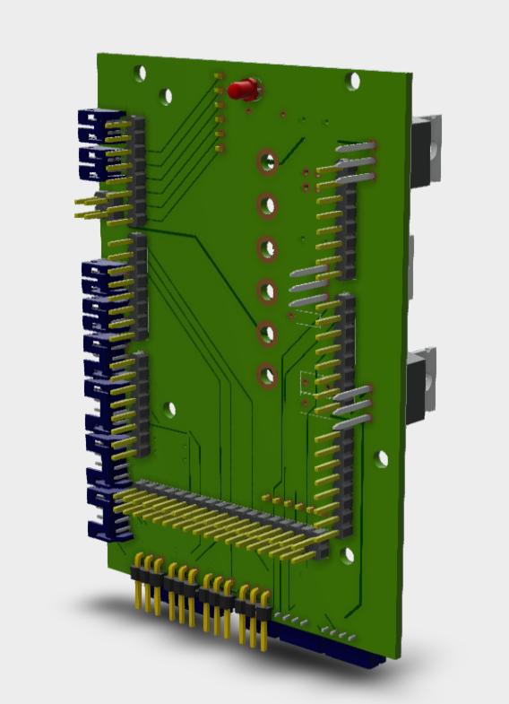
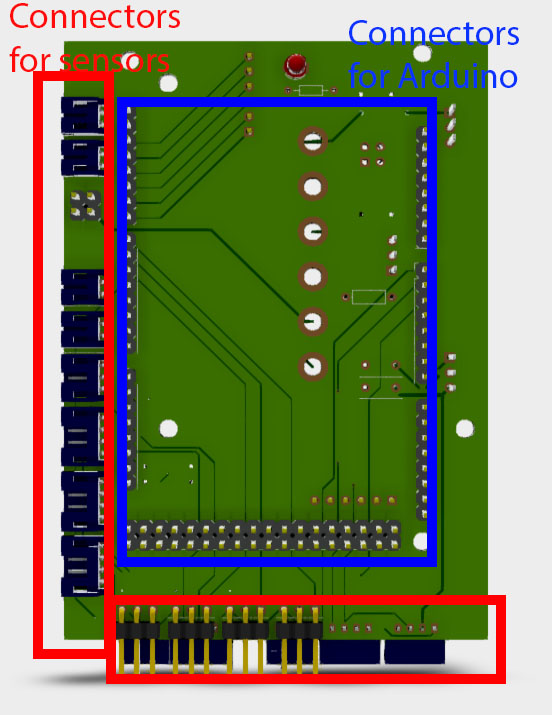
Custom board
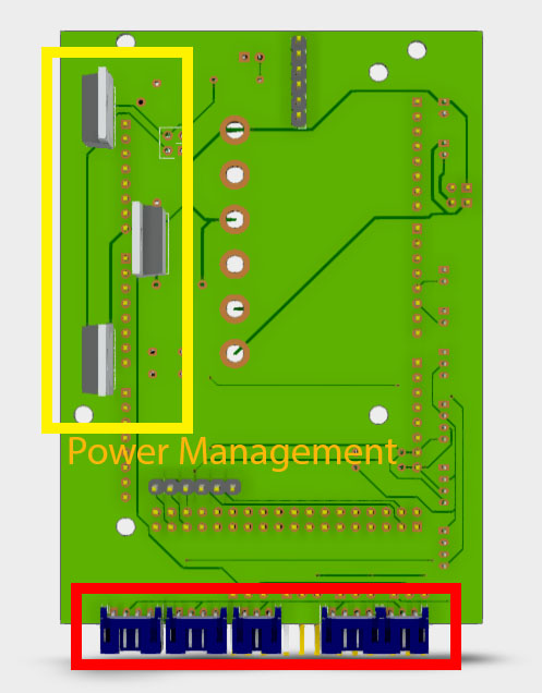
This custom board in question, as I said, is to manage the power comming from the battery and dispatch it to all the sensors and the main computers (Arduino and Raspberry Pi). It’s also installed with industrial connectors - JSTs - for robustness and is compact so that it can be mounted in any boats, even small ones.
Therefore, it is not that complex of a board : 3 regulators for the raspberry pi, the motors and the Arduino, and the sensors. These regulators converts the battery input (any voltage from 5V to 24V) to 5V constant for all the components. Most of the pins from the Arduino are linked to JST connectors to connect the sensors to the board securely, instead of connecting them on the socket header of the arduino (which is really not robust). And that’s about it.
The board connects to boath the Arduino and another custom board which connects to the Raspberry Pi. They stack altogether in a 70mm x 130mm x 50mm Volume.
Connections
This stack of board that makes our main computer for our autonomous boats is then connected to all the sensors and motors of the boat to make it fully autonomous. Check the next post to see what software goes inside this hardware.